Guide · about 7 min read
How to make a sheet metal flat pattern: K-factor, bend table, DXF
The flat pattern is the flat shape of a bent sheet metal part, the shape the laser cuts. To get it right you need to know how much the sheet stretches in each bend, the bend allowance, and that depends on the K-factor. SelviCAD does the calculation for you: you model the part, press Açınım (Flatten) and hand the DXF to the laser shop.
About the language: SelviCAD's interface is in Turkish today; an English UI is coming soon. Menu and button names are written in Turkish as they appear on screen, with the English meaning in brackets.
Why calculate a flat pattern?
When sheet metal bends, the inside face gets shorter and the outside face gets longer. Between them is a line whose length does not change: the neutral axis. The flat length is calculated along that axis. If you simply add up the outside dimensions of the part, the cut blank comes out too long and the bent part is off size.
The flat length is the sum of the straight segments plus the allowance of each bend. The bend allowance is the arc of the bend measured along the neutral axis.
What is the K-factor, and what value to use?
The K-factor is the distance of the neutral axis from the inside face of the sheet, divided by the sheet thickness. It is a number between 0 and 1 (SelviCAD does not accept values outside this range); in practice it is usually between 0.3 and 0.5. The smaller the inner radius compared with the thickness, the smaller K gets.
Bend allowance = angle (radians) × (R + K × t)
R is the inner bend radius and t the sheet thickness; 90° is about 1.5708 radians. SelviCAD uses K = 0.44 by default. If you tick “K faktörünü tablodan al” (take the K-factor from the table) in the Abkant (press brake) section of the Taban Flanş panel, K comes from the table below, by material, thickness and inner radius.
| Material | R/t = 0.5 | R/t = 1 | R/t = 2 | R/t = 3 | R/t = 5 |
|---|---|---|---|---|---|
| Steel (S235, S355, cold-rolled) | 0.33 | 0.38 | 0.42 | 0.44 | 0.47 |
| Stainless steel | 0.36 | 0.40 | 0.44 | 0.46 | 0.48 |
| Aluminium | 0.30 | 0.35 | 0.40 | 0.43 | 0.46 |
| Copper / brass | 0.30 | 0.35 | 0.39 | 0.42 | 0.45 |
These are starting values. The real K depends on the machine, the tooling and the batch of material; your machine's table and a test bend are what count. You can write the values you measure into the K table in Abkant Tablosu (Press Brake Table) and return to the defaults at any time.
Step by step: from sheet metal part to DXF
To start from a ready example, open Dosya → Örnekler → Sac kutu (açınımlı) (File → Examples → Sheet metal box, with flat pattern): 1.5 mm sheet, four edge flanges and mounting holes are already there. For your own part, the steps are:
Draw the sheet metal sketch
On the Sac Levha (Sheet Metal) tab, press Eskiz (Sketch), pick a plane, draw the flat outline of the part as a closed profile and dimension it; exit the sketch. If you draw an open line instead, you get a bent strip: the corners become bends and you enter the width separately.
Make it sheet metal with Taban Flanş
Enter the sheet thickness, the inner bend radius and the K-factor (default K 0.44). If you choose an “Alt kalıp” (die) in the Abkant section, the bend radius becomes the air-bending radius of that die.
Bend the edges
Press Kenar Flanşı (Edge Flange), pick a straight edge, and enter the length and angle (default 90°). The same tab also has Kenar Kıvırma (Hem), Çevresel Flanş (Miter Flange, a chain of flanges whose corners close with mitres), Kademe (Jog) and Çizgiyle Büküm (Sketched Bend); Açılı Flanş is preset for 45°.
Add holes and cut-outs
Open holes or slots with Eskiz and Kesme (Cut), or with Delik Sihirbazı (Hole Wizard). Tasarım Denetimi (Design Check) on the Hesapla tab tells you when a hole is too close to an edge or a bend: in sheet metal, expect at least 2 × thickness to an edge or another cut-out, and at least 2.5 × thickness + bend radius to a bend.
Press Açınım
The part flattens and the bend lines appear. Press the same button again (or suppress Açınım in the tree) and the part returns to its bent state.
Look at the Sac Kesim Listesi
You see the flat size (length × width), the cut length, the number of holes and bends, the mass and the bend table. You can save it as Excel (.xlsx) or CSV.
Save the file with DXF Al
Press DXF Al (Export DXF) on the Sac Levha tab. The file is in millimetres; bend lines and notes are on separate layers (see below).
Plan the press brake and the sheet if needed
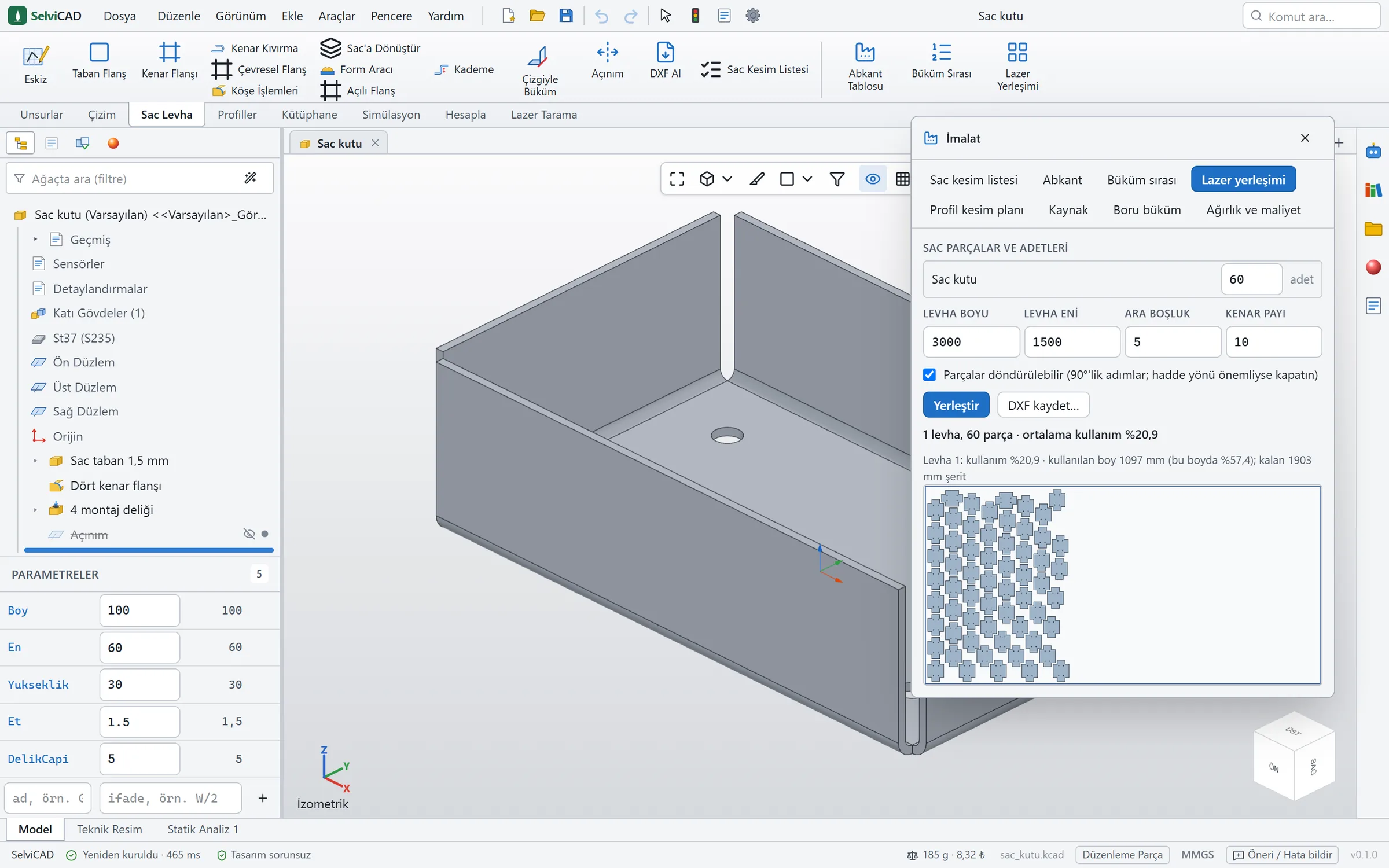
Büküm Sırası (Bend Sequence) shows which bend comes first on the press brake; at each step you follow on the model whether the part hits the punch, the die or the machine. Lazer Yerleşimi (Laser Nesting) lays out the flat patterns of the parts you choose on the sheet with as little scrap as possible and gives one DXF with the sheet usage percentage.
Check by hand: a small example
To see how the calculation works: a 100 × 60 mm plate, 2 mm thick, with a 20 mm, 90° edge flange on its 60 mm top edge. Inner radius 2 mm, K = 0.44.
- Bend allowance: 1.5708 × (2 + 0.44 × 2) = 1.5708 × 2.88 ≈ 4.52 mm.
- Straight part of the flange: the flange length is the height measured from the outside face of the sheet; the outer radius of the bend (2 + 2 = 4 mm) comes off it: 20 − 4 = 16 mm.
- Width of the flat pattern: 60 + 4.52 + 16 = 80.52 mm. The length stays 100 mm.
In the Sac Kesim Listesi, the Açınım column should show about 100 × 80.5. If you take K from the table (0.38 for steel at R/t = 1), the bend allowance becomes 4.34 mm; 0.19 mm looks small for one bend, but on a part with four bends the difference approaches 0.75 mm. That is why you confirm the first part with a test bend.
Bend table and press brake
Two different tables are useful.
Bend list: Sac Kesim Listesi
Below the flat size, each bend of the part is listed on one row. This is the table you give to the press brake operator; you export it to Excel.
| Column | Meaning |
|---|---|
| Büküm | Bend number (1, 2, 3…) |
| Yön | Direction: up or down |
| Açı | Bend angle (degrees) |
| İç yarıçap | Inner radius of the bend (mm) |
| Boy | Length of the bend line (mm) |
Abkant Tablosu (Press Brake Table)
The Abkant Tablosu on the Sac Levha tab shows, by material and thickness: the die (V opening), the inner radius produced in air bending, K, the bending force per metre (kN/m) and the shortest flange that can be bent in that die. You can add your own V openings to the die list. As a rule of thumb, for sheet up to 3 mm the die opening is about 6 times the thickness, for example V12 for 2 mm sheet.
Press brake values are estimates. The machine maker's table and a test bend are what count.
The DXF layers
SelviCAD writes the lines to be cut on separate layers from the bend-related lines. The laser operator picks the cutting layer, and the press brake operator reads the bend notes.
| Layer | What is on it | Line |
|---|---|---|
| OUTLINE | The outer contour of the part and the holes: the lines the laser cuts | Black, continuous |
| BEND | The edge lines of the bend zone | Red, dashed |
| BEND_CENTER | The axis of the bend | Red, dash-dot |
| BEND_NOTES | A note for each bend with direction, angle and inner radius: “YUKARI 90° R2” | Red text |
| FORM_TOOL | Outline and centre mark of forming tools such as louvers and round embosses (if any) | Magenta |
The bend notes are written in Turkish: YUKARI means up and AŞAĞI means down. The DXF is written with the Turkish code page so that letters such as Ş read correctly in older CAM programs too.
Before you send it to the laser shop
- Put the material and thickness in the file name or a note.
- Say which layer to cut. The cut lines are on the OUTLINE layer; the bend layers are for information. The shop's CAM program may handle layers differently.
- Send the Sac Kesim Listesi as Excel alongside, for quantities and mass.
- Share the bend direction notes (YUKARI / AŞAĞI, up / down) with the press brake operator.
- Confirm the first part by bending it; if it is off size, correct the K table with the value you measured.
Frequently asked questions
What K-factor should I use?
To start, SelviCAD's default of 0.44; taking it from the table by material is more accurate. The exact value depends on the machine, the tooling and the material: confirm it with a test bend and write the value you measure into the K table.
The flat size does not match the real bend. What should I do?
First check the real inner radius and the K-factor. In air bending, the real inner radius depends on the die opening; if you choose the die you bend with in the Taban Flanş panel, the radius is taken from that die.
Can I turn a bent solid model into a sheet metal part?
Yes. Sac'a Dönüştür (Convert to Sheet Metal) turns a plate with thickness, or a bent solid such as a hollowed box or a U channel, into a sheet metal part: you click the base face of the solid, the walls and bends are recognised, and sharp corners are rounded with the radius you give. Then the flat pattern and cut list work.
Which programs open the flat pattern DXF?
DXF opens in most laser and CNC programs. The file is written in millimetres.
What if holes end up too close to a bend?
A hole too close to the bend zone can distort while bending; Tasarım Denetimi warns you. Move the hole at least 2.5 × thickness + bend radius away from the bend.
Try it on your own sheet metal part.
Try it free for 30 days with every feature included. Fill in the form for a trial key and a personal download link.